DIYIR - Soldering Kit: Difference between revisions
No edit summary |
|||
| Line 9: | Line 9: | ||
== Assemly Instructions == | == Assemly Instructions == | ||
Follow the step by step guide [[DIYIR Assembly Instructions]] | Follow the step by step guide [[DIYIR Assembly Instructions]] | ||
== Connection Header P1 == | |||
You can use Header P1 to connect the DIYIR module to your Microcontroller. Check out the section below about wiring to an Arduino UNO. Each signal appears twice on P1, in case you need to daisy-chain any of the signals or just for testing with a multimeter or oscilloscope. | |||
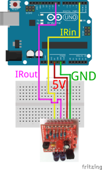
'''+ Pin''' - Connect this to the power rail of your microcontroller. Usually if your MCU is powered from 5V via USB and runs at 5V this is suffiecient. (If your MCU is powered from 3V3 then connect this pin to the 3V3 rail of your MCU). | |||
'''- Pin''' - This is the ground pin and should be connected to the GND pin of your MCU. | |||
'''IN Pin''' - This is the IRin pin for your MCU and on the UNO is connected to Pin2 (or any other pin you designate in your firmware) | |||
'''OUT Pin''' - This is the IRout pin for your MCU and on the UNO is connected to Pin9 (which is the default for Irremote or any other pin you designate in your firmware) | |||
== Jumper Settings == | == Jumper Settings == | ||
Revision as of 05:34, 19 September 2018
Where To Purchase
Visit AnalysIR's IR Shop where you will find this and a range of similar Infrared solutions. You can also purchase via our Tindie Store
Data Sheet
The data sheet can be found by clicking here
Assemly Instructions
Follow the step by step guide DIYIR Assembly Instructions
Connection Header P1
You can use Header P1 to connect the DIYIR module to your Microcontroller. Check out the section below about wiring to an Arduino UNO. Each signal appears twice on P1, in case you need to daisy-chain any of the signals or just for testing with a multimeter or oscilloscope. + Pin - Connect this to the power rail of your microcontroller. Usually if your MCU is powered from 5V via USB and runs at 5V this is suffiecient. (If your MCU is powered from 3V3 then connect this pin to the 3V3 rail of your MCU). - Pin - This is the ground pin and should be connected to the GND pin of your MCU. IN Pin - This is the IRin pin for your MCU and on the UNO is connected to Pin2 (or any other pin you designate in your firmware) OUT Pin - This is the IRout pin for your MCU and on the UNO is connected to Pin9 (which is the default for Irremote or any other pin you designate in your firmware)
Jumper Settings
JP1 - Insert this to increase IR Output power by a factor of 2x.
JP2 - Set to 5V for 5V operation and to 3V3 for 3V3 operation. (In 3V3 mode one of the IR emitters is removed from the circuit)
Note, it may be possible to operate both emitters @ 3V3 by powering from 3V3 and setting JP2 to 5V mode, However, the red LED may not visibly blink when a signal is being sent.
Always make sure to power the module from the same voltage as the locic level of the system you are connecting to (5v->5V or 3V3->3V3 DO NOT mix voltage levels or you will damage your MCU or module)
Use with IRRemote
DIYIR can be used with IRremote and othe Libraries(E.g. IRLib) by connecting as follows:

The image shows wiring for %V opertion. To use with 3V3 set the position of JP2 accordingly.