KontroLIR - Arduino compatible IR remote control: Difference between revisions
(Created page with "Arduino compatible IR remote control work in progress") |
mNo edit summary |
||
| Line 1: | Line 1: | ||
Arduino compatible IR remote | '''KontroLIR – 100% Arduino compatible IR remote Control, with optional extras | ||
work in progress | work in progress''' | ||
== Where To Purchase == | |||
KontroLIR is available in our store and can be purchased via [https://www.analysir.com/blog/shop// Buy KontroLIR]. | |||
KontroLIR is comprised of twin modules, one for Tx and the other for Rx. It is also possible to use the Tx module as a 38kHz IR transmitter and the Rx module as a general purpose 38kHz IR receiver. | |||
== Data Sheet == | |||
The data sheet can be found by [https://www.analysir.com/blog/product-sheet-kontrolir_reva/ clicking here] | |||
== Applications == | |||
KontroLIR, can be used in the following: | |||
* Light Barriers | |||
* Security projects | |||
* Lap Timers | |||
BeamIR can be used in both 'beam mode' where the 2 modules are placed at either end of the invisible beam and in 'reflective mode' where the IR is bounced or reflected off a target and both modules are placed side by side facing the target. | |||
== KontroLIR Pin Out Serial Interface == | |||
[[File:KontroLIR Serial Interface.jpg|frameless|Serial interface pinout]] | |||
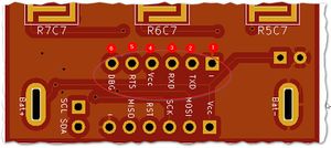
The header pins for the Serial I/F interface are laid out as follows: | |||
* '''GND''' -ve supply power Ground / 0V | |||
* '''TXD''' Connects to TXD on the adapter (Connected to TXD0 on the ATmega328PB) | |||
* '''RXD''' Connects to RXD on the adapter (Connected to RXD0 on the ATmega328PB) | |||
* '''VCC''' +ve supply power 5V (will also work with a 3V3 supply @ 8MHz or 4MHz) | |||
* '''RTS''' Used to reset the MCU during Firmware upload | |||
* '''DBG''' Unpopulated by default. Can be used as a debug pin, if necessary. Also connected to the LED. | |||
''Note 1: The image is looking from the keypad up. Looking throught the battery compartment, the order will be mirrored.'' | |||
== BeamIRtx Pin Out ICSP == | |||
[[File:KontroLIR ICSP Header.jpg|frameless|Serial interface pinout]] | |||
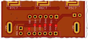
The header pins for the AVR ICSP interface are laid out as follows: | |||
* '''GND''' -ve supply power Ground / 0V | |||
** '''MISO''' Standard ICSP pin for use with avrdude & USBASP, Atmel ICE programmer or equivalent | |||
** '''RESET''' Standard ICSP pin for use with avrdude & USBASP, Atmel ICE programmer or equivalent | |||
** '''SCK''' Standard ICSP pin for use with avrdude & USBASP, Atmel ICE programmer or equivalent | |||
** '''MOSI''' Standard ICSP pin for use with avrdude & USBASP, Atmel ICE programmer or equivalent | |||
* '''VCC''' +ve supply power 5V | |||
== Basic Functionality == | |||
Whne a Tx & Rx module are configured correctly and operational the outputs will be as follows: | |||
'''IR Beam not broken''' | |||
* OUT => Logic LOW (Close to 0V) | |||
* OUT2 => Logic HIGH (Close to VCC, via pull-up resistor) | |||
* OC => Open Collector, shorted to GND via NPN/CE (Driven by OUT2) | |||
* Red LED => ON | |||
'''IR Beam broken''' | |||
* OUT => Logic High(Close to VCC) | |||
* OUT2 => Logic LOW(Close to GND, via NPN/CE) | |||
* OC => Open Collector, Open & connected to NPN collector, which is 'turned off' | |||
* Red LED => OFF | |||
== Range == | |||
The effective range of BeamIR can be from 1m to 20m+ depending on the IR Power setting and ambient lighting. However, it is important to note: | |||
* The further the range the wider the IR Beam, So it may help to reduce the beam width, by using an opaque pipe for direction. | |||
* Sunshine can interfere with IR transmission. The carrier frequency helps mitigate errors due to sunshine. Pulsing the Tx module at say 600uSecs can help distinguish between valid beam signals and interference. | |||
* If sunshine is a factor, placing the receiver unit on the side pointing away from the Sun, will help. | |||
* Much longer ranges and narrower beams can be achieved by the use Optics/lenses to focus the beam. | |||
== Configurations == | |||
It is possible to use BeamIR in various configurations | |||
* 5V or 3V3 mode | |||
* x1, x2, x3 or custom IR Power | |||
* As a 38kHz IR emitter (Tx Module) | |||
* As a general purpose IR receiver (Rc Module). Excellent performance across multiple IR protocols & carrier Frequencies. | |||
* Using Logic Lever or OC output. | |||
* Multiple Rx modules with a single tx module | |||
* Combination of multiple Tx & Rx modules (e.g. virtual fence enclosing an area) | |||
* With optics and/or shielding (Pipes/light barriers) to improve range & performance. | |||
== Getting Support == | |||
If you need additional support please open a new issue in our IRforum - under Products:Support Requests. | |||
== More Information == | |||
If... | |||
* There is a topic not covered here or | |||
* You would like us to add some more information or | |||
* You have a tip to add or | |||
* you have noticed a mistake | |||
then let us know via the [https://www.analysir.com/blog/contact/ contact page] | |||
Revision as of 09:05, 8 July 2019
KontroLIR – 100% Arduino compatible IR remote Control, with optional extras
work in progress
Where To Purchase
KontroLIR is available in our store and can be purchased via Buy KontroLIR.
KontroLIR is comprised of twin modules, one for Tx and the other for Rx. It is also possible to use the Tx module as a 38kHz IR transmitter and the Rx module as a general purpose 38kHz IR receiver.
Data Sheet
The data sheet can be found by clicking here
Applications
KontroLIR, can be used in the following:
- Light Barriers
- Security projects
- Lap Timers
BeamIR can be used in both 'beam mode' where the 2 modules are placed at either end of the invisible beam and in 'reflective mode' where the IR is bounced or reflected off a target and both modules are placed side by side facing the target.
KontroLIR Pin Out Serial Interface
The header pins for the Serial I/F interface are laid out as follows:
- GND -ve supply power Ground / 0V
- TXD Connects to TXD on the adapter (Connected to TXD0 on the ATmega328PB)
- RXD Connects to RXD on the adapter (Connected to RXD0 on the ATmega328PB)
- VCC +ve supply power 5V (will also work with a 3V3 supply @ 8MHz or 4MHz)
- RTS Used to reset the MCU during Firmware upload
- DBG Unpopulated by default. Can be used as a debug pin, if necessary. Also connected to the LED.
Note 1: The image is looking from the keypad up. Looking throught the battery compartment, the order will be mirrored.
BeamIRtx Pin Out ICSP
The header pins for the AVR ICSP interface are laid out as follows:
- GND -ve supply power Ground / 0V
- MISO Standard ICSP pin for use with avrdude & USBASP, Atmel ICE programmer or equivalent
- RESET Standard ICSP pin for use with avrdude & USBASP, Atmel ICE programmer or equivalent
- SCK Standard ICSP pin for use with avrdude & USBASP, Atmel ICE programmer or equivalent
- MOSI Standard ICSP pin for use with avrdude & USBASP, Atmel ICE programmer or equivalent
- VCC +ve supply power 5V
Basic Functionality
Whne a Tx & Rx module are configured correctly and operational the outputs will be as follows:
IR Beam not broken
- OUT => Logic LOW (Close to 0V)
- OUT2 => Logic HIGH (Close to VCC, via pull-up resistor)
- OC => Open Collector, shorted to GND via NPN/CE (Driven by OUT2)
- Red LED => ON
IR Beam broken
- OUT => Logic High(Close to VCC)
- OUT2 => Logic LOW(Close to GND, via NPN/CE)
- OC => Open Collector, Open & connected to NPN collector, which is 'turned off'
- Red LED => OFF
Range
The effective range of BeamIR can be from 1m to 20m+ depending on the IR Power setting and ambient lighting. However, it is important to note:
- The further the range the wider the IR Beam, So it may help to reduce the beam width, by using an opaque pipe for direction.
- Sunshine can interfere with IR transmission. The carrier frequency helps mitigate errors due to sunshine. Pulsing the Tx module at say 600uSecs can help distinguish between valid beam signals and interference.
- If sunshine is a factor, placing the receiver unit on the side pointing away from the Sun, will help.
- Much longer ranges and narrower beams can be achieved by the use Optics/lenses to focus the beam.
Configurations
It is possible to use BeamIR in various configurations
- 5V or 3V3 mode
- x1, x2, x3 or custom IR Power
- As a 38kHz IR emitter (Tx Module)
- As a general purpose IR receiver (Rc Module). Excellent performance across multiple IR protocols & carrier Frequencies.
- Using Logic Lever or OC output.
- Multiple Rx modules with a single tx module
- Combination of multiple Tx & Rx modules (e.g. virtual fence enclosing an area)
- With optics and/or shielding (Pipes/light barriers) to improve range & performance.
Getting Support
If you need additional support please open a new issue in our IRforum - under Products:Support Requests.
More Information
If...
- There is a topic not covered here or
- You would like us to add some more information or
- You have a tip to add or
- you have noticed a mistake
then let us know via the contact page

