KontroLIR Pin Outs: Difference between revisions
m (→GPIO Mapping) |
m (→GPIO Mapping) |
||
| Line 50: | Line 50: | ||
The contents should be relatively straight forward to follow, for those familiar with the Arduino and IRremote ecosystems. | The contents should be relatively straight forward to follow, for those familiar with the Arduino and IRremote ecosystems. | ||
The image below shows the mapping between MCU pins, Aruino pins and function used in KontroLIR. | |||
[[File:KontrolIR_Pin_Map.jpg]] | |||
Revision as of 03:13, 6 October 2019
KontroLIR Pin Out Serial Interface
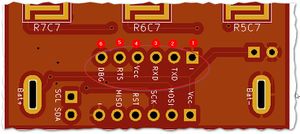
The header pins for the Serial I/F interface are laid out as follows:
- GND -ve supply power Ground / 0V
- TXD Connects to TXD on the adapter (Connected to TXD0 on the ATmega328PB)
- RXD Connects to RXD on the adapter (Connected to RXD0 on the ATmega328PB)
- VCC +ve supply power 5V (will also work with a 3V3 supply @ 8MHz or 4MHz)
- RTS Used to reset the MCU during Firmware upload
- DBG Unpopulated by default. Can be used as a debug pin, if necessary. Also connected to the LED.
Note 1: The image is looking from the keypad up. Looking throught the battery compartment, the order will be mirrored.
Note 2: On my FTDI Serial USB adapter: RTS=>DTR; RXD=>Tx;TXD=>Rx; GND=>GND; VCC=>5V.
Note 3: These pins are accessible via the battery compartment.
KontroLIR Pin Out ICSP
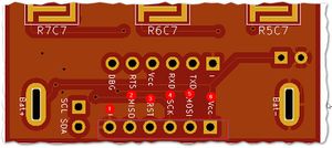
The header pins for the AVR ICSP interface are laid out as follows:
- GND -ve supply power Ground / 0V
- MISO Standard ICSP pin for use with avrdude & USBASP, Atmel ICE programmer or equivalent
- RESET Standard ICSP pin for use with avrdude & USBASP, Atmel ICE programmer or equivalent
- SCK Standard ICSP pin for use with avrdude & USBASP, Atmel ICE programmer or equivalent
- MOSI Standard ICSP pin for use with avrdude & USBASP, Atmel ICE programmer or equivalent
- VCC +ve supply power 5V
Note 1: To access these pins you must first remove the batteries and then 'carefully' open the enclosure.
Misc
There are other headers available for advanced users, as follows:
- 2-pin through hole I2C interface (SDA,SCL)
- 4-pin SMD I2C interface (SDA,SCL,VCC,GND)
- If IR receivers are not installed, then the footprints are available, along with the associated GPIO pins.
- If the I2C EEPROM is not installed, then the SOIC-8 footprint is available, along with the associated GPIO pins.
Spare GPIOs
Advanced users, may further expand KontroLIR, using the following GPIOs, if available.
- The LED pin may be reused for other purposes, if desired. (1 GPIO)
- If the IR receivers are not installed, the 2 signal pins & power supply pin may be reused. (3 GPIOs)
- If the I2C EEPROM is not used then the SDA & SCL pins & power supply pin may be reused. (3 GPIOs)
GPIO Mapping
Detailed GPIO mapping can be examined in the file: KIR_header.h Remote button IDs are pre-calculated from the ROW/COL indices. Every pin used is pre-defined along with a collection of useful pre-compiler macros, intended for easue of use. The contents should be relatively straight forward to follow, for those familiar with the Arduino and IRremote ecosystems.
The image below shows the mapping between MCU pins, Aruino pins and function used in KontroLIR.


