DIYIR - Soldering Kit
Summary
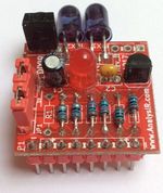
DIYIR is a kit for building a high-end fully functioning IR transmitter and receiver. Soldering skills are required along with solder and a soldering iron. An MCU or microcontroller is also required to control the module.
Beginners can build the module as part of a soldering class or course under supervision. Experienced users can use the kit to complete their own high-end IR module.
The kit uses high quality IR components from Vishay. We also include dual IR LEDs with the kit which have narrow and wider angles for greater coverage in most situations.
See below for how instructions on how you can get your free Bonus firmware for your DIYIR kit.
Where to Purchase

Visit AnalysIR's IR Shop where you will find this and a range of similar Infrared solutions. You can also purchase DIYIR via our Tindie Store
Included Components: PCB x1, IR Receiver x1, IR LEDs x2, Red Led x1, Resistors x6, Capacitors x2, Transistor x1, 5 Pin Header x1, 8 Pin Header x1, Jumpers x2. You should receive a total of 18 parts included with your DIYIR kit.
Data Sheets
The data sheet for the DIYIR module can be found by clicking here
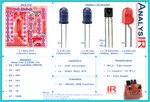
The data sheets for the main components are available via the links below:
IRx1 or IRx2 IR Receiver - TSSP4038
D2 IR LED #1 - TSAL6100
D3 IR LED #2 - TSAL6200
Q1 NPN Transistor - 2N4401
Always mare sure to check & verify the pinouts of components, before installing and applying power. (TIP: The longer lead of LEDs is the +ve side and the shorter leg is the -ve side)
Assembly Instructions
Follow the step by step guide DIYIR Assembly Instructions
Connection Header P1
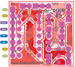
You can use Header P1 to connect the DIYIR module to your Microcontroller. Check out the section below about wiring to an Arduino UNO. Each signal appears twice on P1, in case you need to daisy-chain any of the signals or just for testing with a multimeter or oscilloscope.
+ Pin - Connect this to the power rail of your microcontroller. Usually if your MCU is powered from 5V via USB and runs at 5V this is sufficient. (If your MCU is powered from 3V3 then connect this pin to the 3V3 rail of your MCU).
- Pin - This is the ground pin and should be connected to the GND pin of your MCU.
IN Pin - This is the IRin pin for your MCU and on the UNO is connected to Pin2 (or any other pin you designate in your firmware)
OUT Pin - This is the IRout pin for your MCU and on the UNO is connected to Pin9 (which is the default for IRremote or any other pin you designate in your firmware)
Jumper Settings
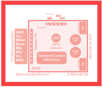
JP1 - Insert this to increase IR Output power by a factor of 2x.
JP2 - Set to 5V for 5V operation and to 3V3 for 3V3 operation. (In 3V3 mode one of the IR emitters is removed from the circuit)
Note, it may be possible to operate both emitters @ 3V3 by powering from 3V3 and setting JP2 to 5V mode. However, the red LED may not visibly blink when a signal is being sent.
Always make sure to power the module from the same voltage as the logic level of the system you are connecting to (5v->5V or 3V3->3V3 DO NOT mix voltage levels or you will damage your MCU or module)
Use with AnalysIR
DIYIR can be used with AnalysIR by wiring it up to an MCU similar to the diagram below. You will receive additional instructions for the most common platforms when you install AnalysIR (Purchase required).
As a bonus, if you post a photo of your completed DIYIR soldering kit, we will provide a free copy of our A.IR shield Nano firmware. Just post the photo to any social media platform or website with a link back to our website and send us a link to your post with your firmware request. With the 'Nano' firmware you get both send & receive ability from AnalysIR, plus free access to our PYTHON script for web based control of sending & receiver IR via RPi (and other platforms supporting PYTHON)
Use with IRremote
DIYIR can be used with IRremote, AnalysIR and other Libraries(e.g. IRLib) by connecting as follows:
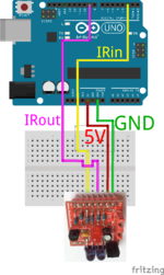
The image shows wiring for 5V operation. To use with 3V3 set the position of JP2 accordingly. To Test try out all of the example sketches provided with the library. By Default IROUT is connected to Pin 9. There is no default for IRIN, but we prefer to use Pin 2, which is the default when using with AnalysIR.
You can find the IRremote library on GitHub. Make sure to read the README before starting.
The latest version of IRLIB is also available via GitHub.
Support Forum
If you have any questions about related to DIYIR kit (and any of our other products) you can post via our IRforum or use the Contact form on our blog. But first search our IRforum and blog for existing answers.